

 注 意
注 意
- この取扱説明書は製品に関わる特記事項についてまとめたものです。
実際の作業や手順については各自動車メーカー発行の整備要領書をご確認ください。 - 本製品は自動車競技部品です。サーキットなどの公道ではない閉鎖された場所で使用してください。
- 本製品の取り付けは設備の整った環境で、資格をもった整備士が行ってください。
- 適合する車種以外へのご使用はおやめください。本製品および、エンジンを破損する恐れがあります。
- 本製品の取り付けに必要な各部品の脱着の際には指定トルクなどを守り、無理な力を加えないで
ください。本製品および、エンジンを破損する恐れがあります。 - 本製品を取り付ける際には、適切な工具、保護具を使用してください。
ご使用にならないとけがにつながり危険です。
警 告
- 本製品の取り付けはエンジンおよび、エキゾースト周辺部品が冷えた状態で作業してください。
- 部品欠落により車両の破損・火災が起こる可能性や、後続・周辺車両へ被害がおよぶおそれがあるため、製品構成部品の取り付けは確実に行ってください。
CAUTION
- The information continued in this installation manual is specific to this product.
For details regarding the removal/installation of stock components, please refer to the vehicle's official servicing manual. - This product is intended for motorsport/competition use and should NOT be used on public roads.
- This product should be installed by a trained professional in a well-equipped workshop.
- Only install this product on the specified vehicle(s) to avoid product and/or engine damage.
- Ensure the appropriate amount of torque is used to remove/install the fastenings. Do NOT use
excessive force as this can damage the product and/or the engine. - Always use the appropriate tools and safety equipment when installing this product.
Failing to do so is extremely dangerous and may result in injury.
WARNING
- Only install this product when the engine and all exhaust related components are cold.
- Ensure that all parts are fitted correctly during installation to avoid potential fire hazards and/or damage. Failing to do so is not only dangerous to you but also those around you.
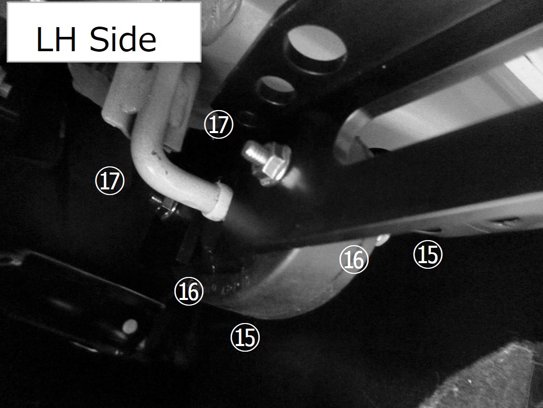
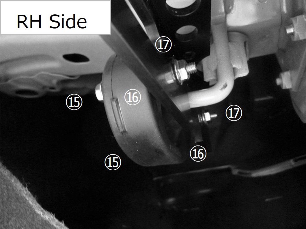
 ここで記載するのは簡易手順です。各部の詳細な脱着方法は、必ず整備要領書を参照してください。
警 告
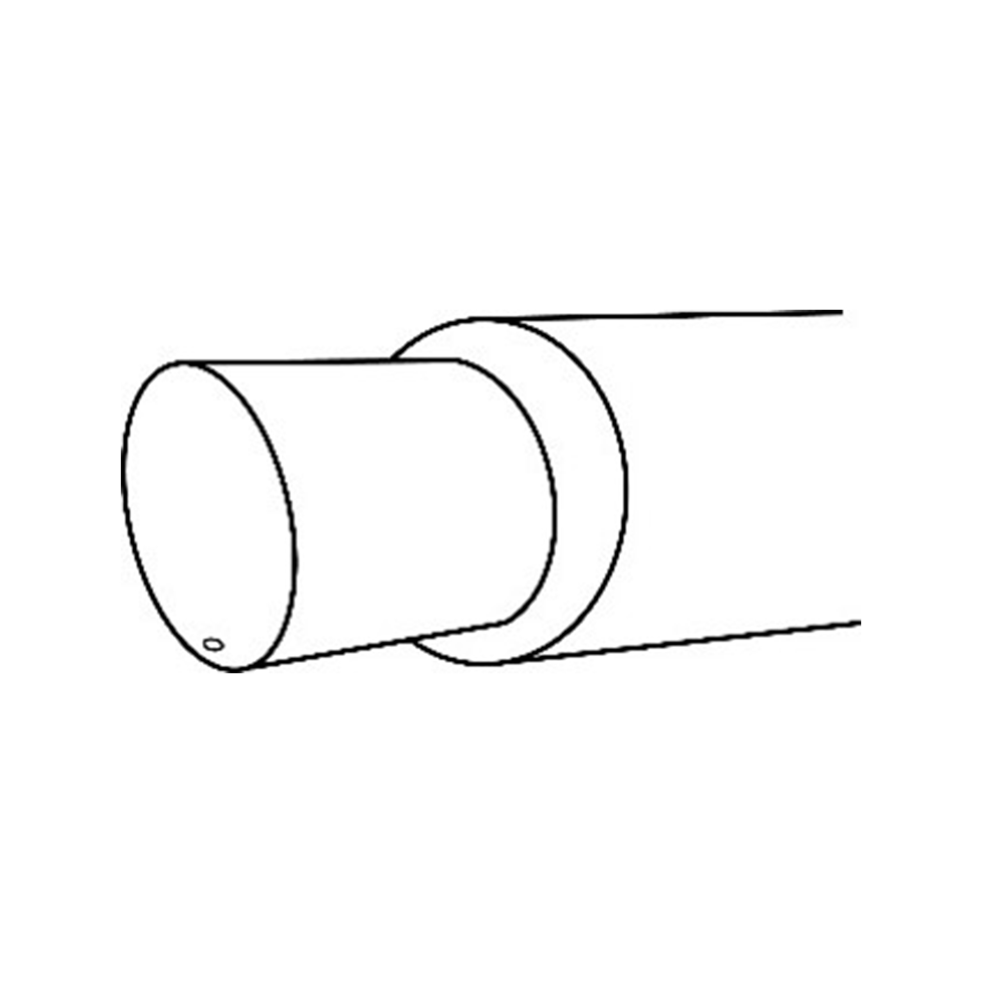
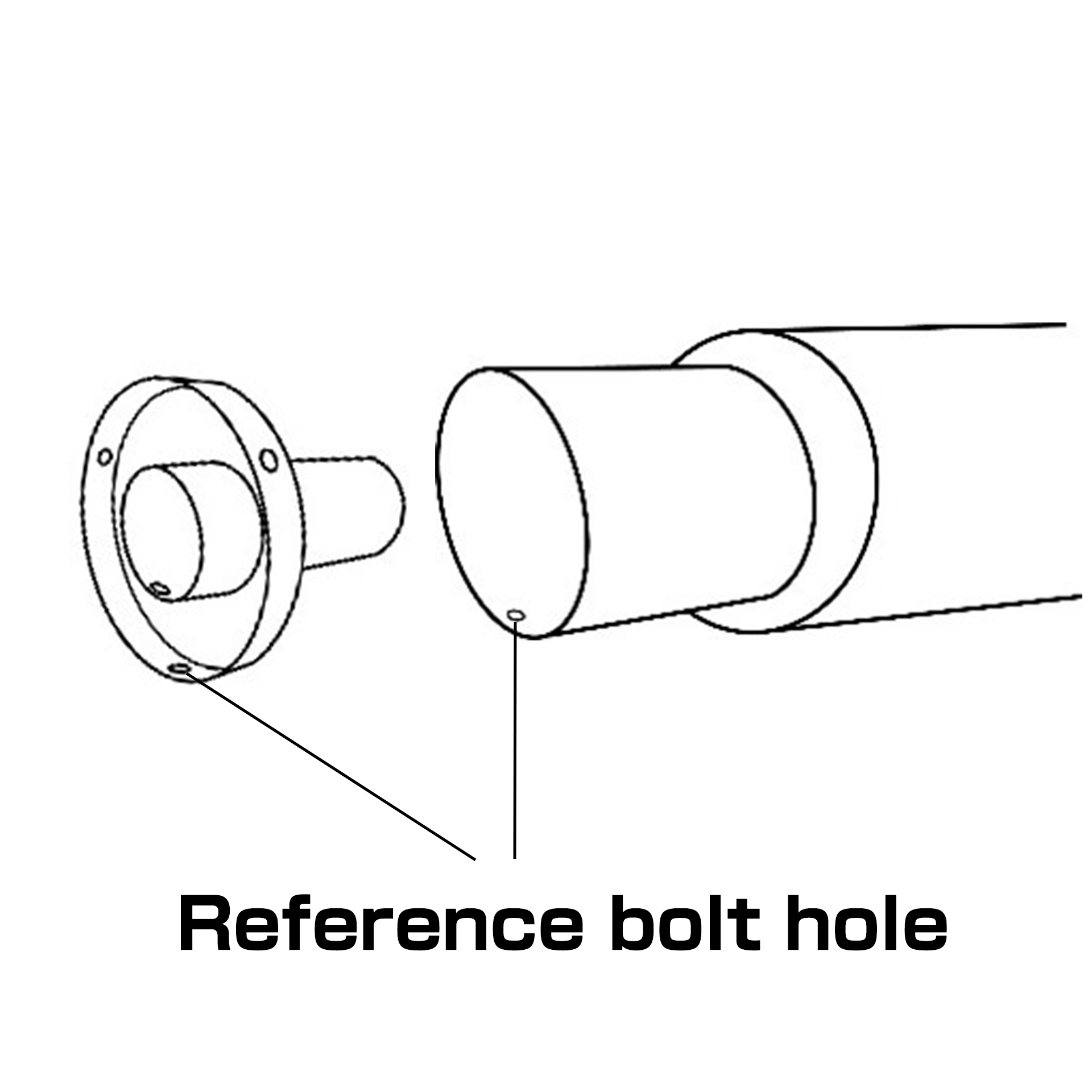
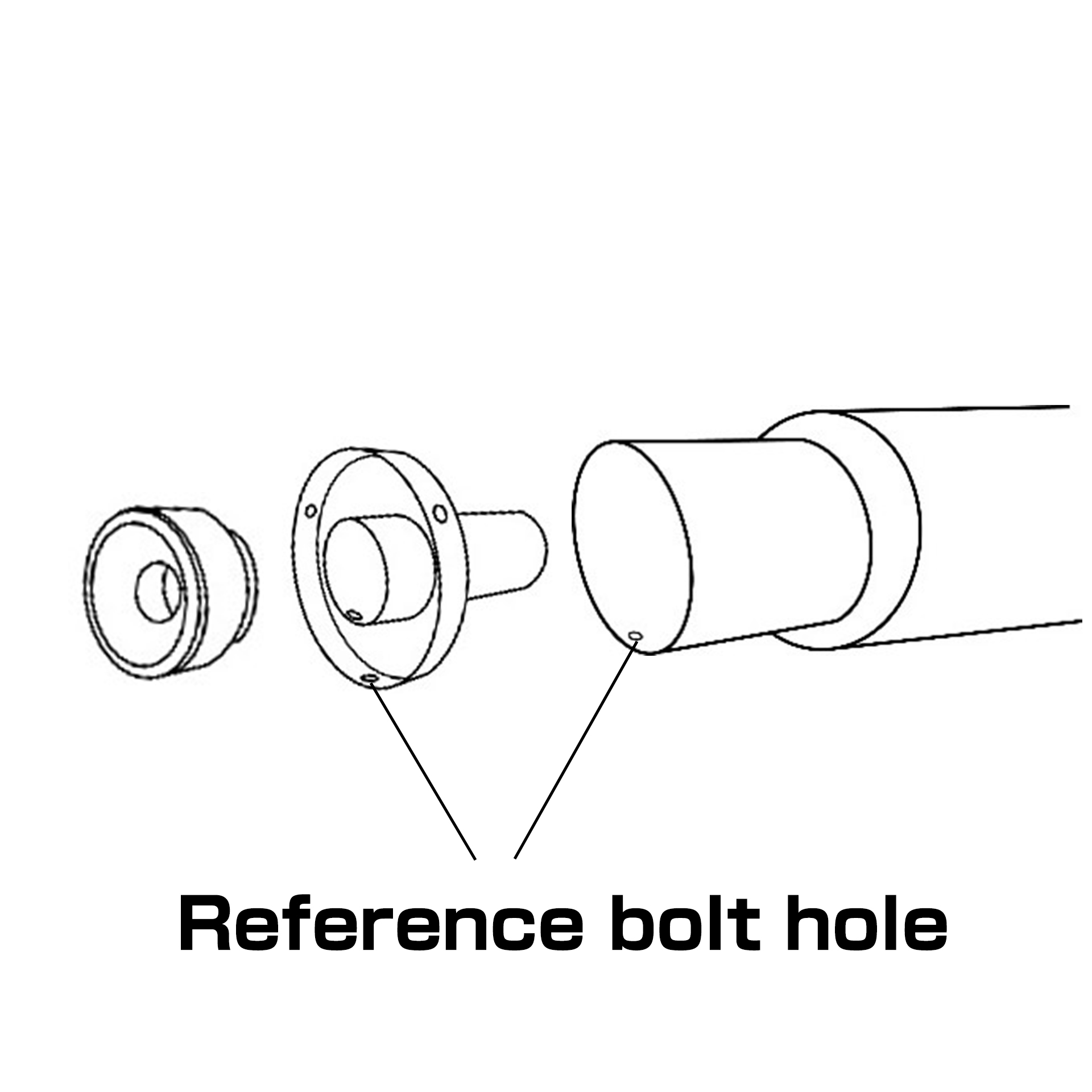
- テールエンドにはあらかじめ取り付け穴が1ヶ所あいていますが、MODE 2の状態でご使用される場合、
必ず下記加工要領を参考に追加工を施して、確実にサウンドレデューサーを固定してください。
なお、MODE 1の状態ではそのままご使用できますが、追加工を行う事でより安全にご使用いただけます。
警 告
- この加工を行なわない場合、部品の欠落により後続・周辺車両へ被害が及ぶ恐れがあります。
- また、サイレンサーテールエンドの変形・破損が起こる場合があります。
注 意
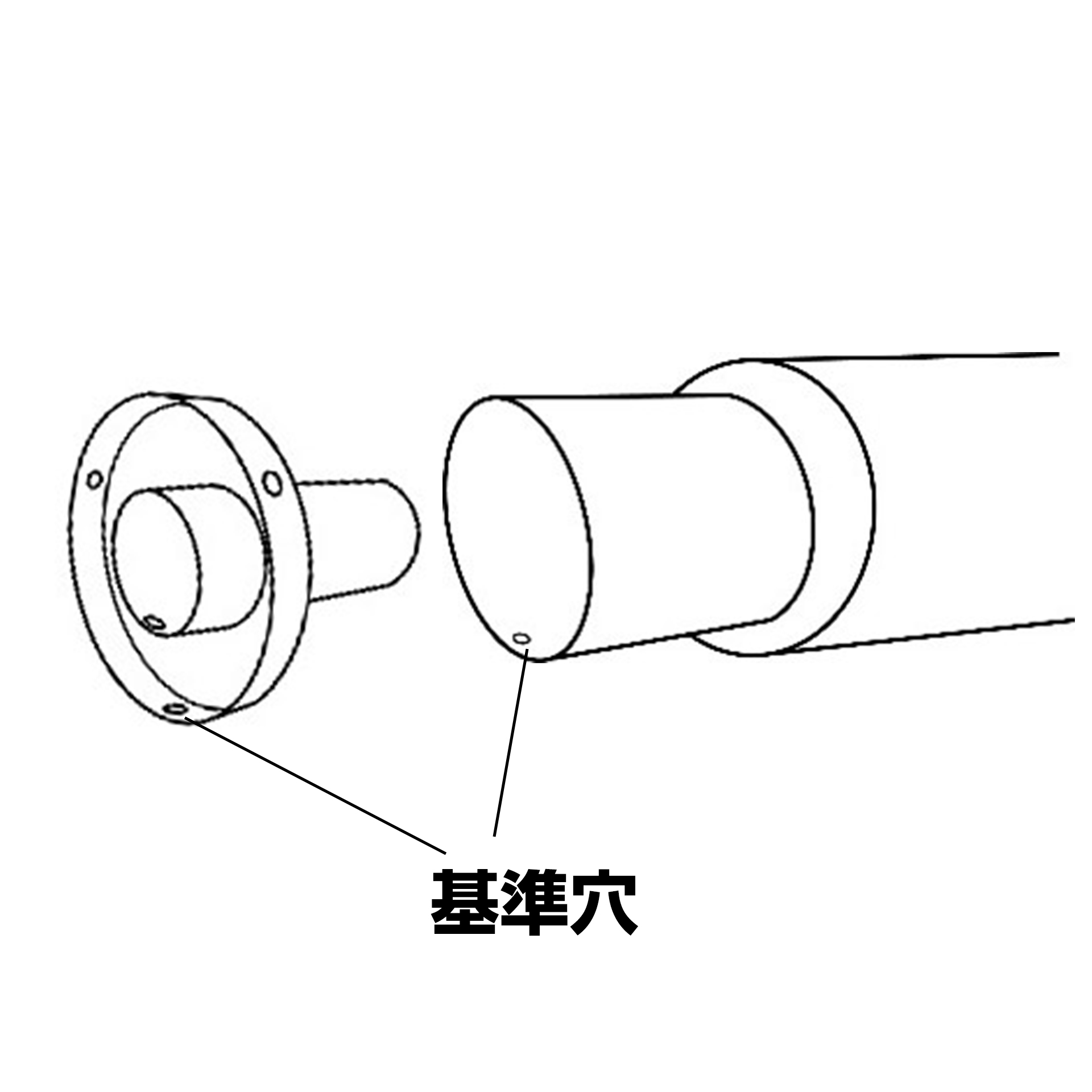
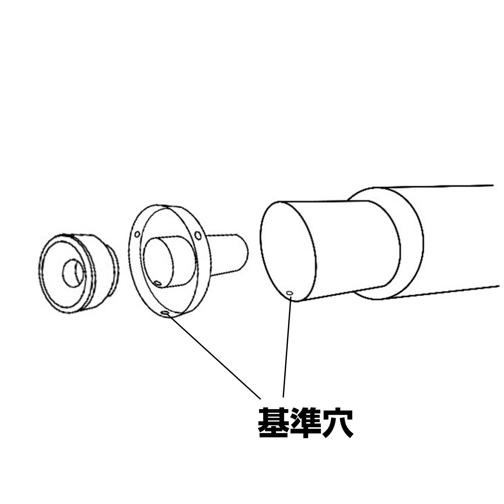
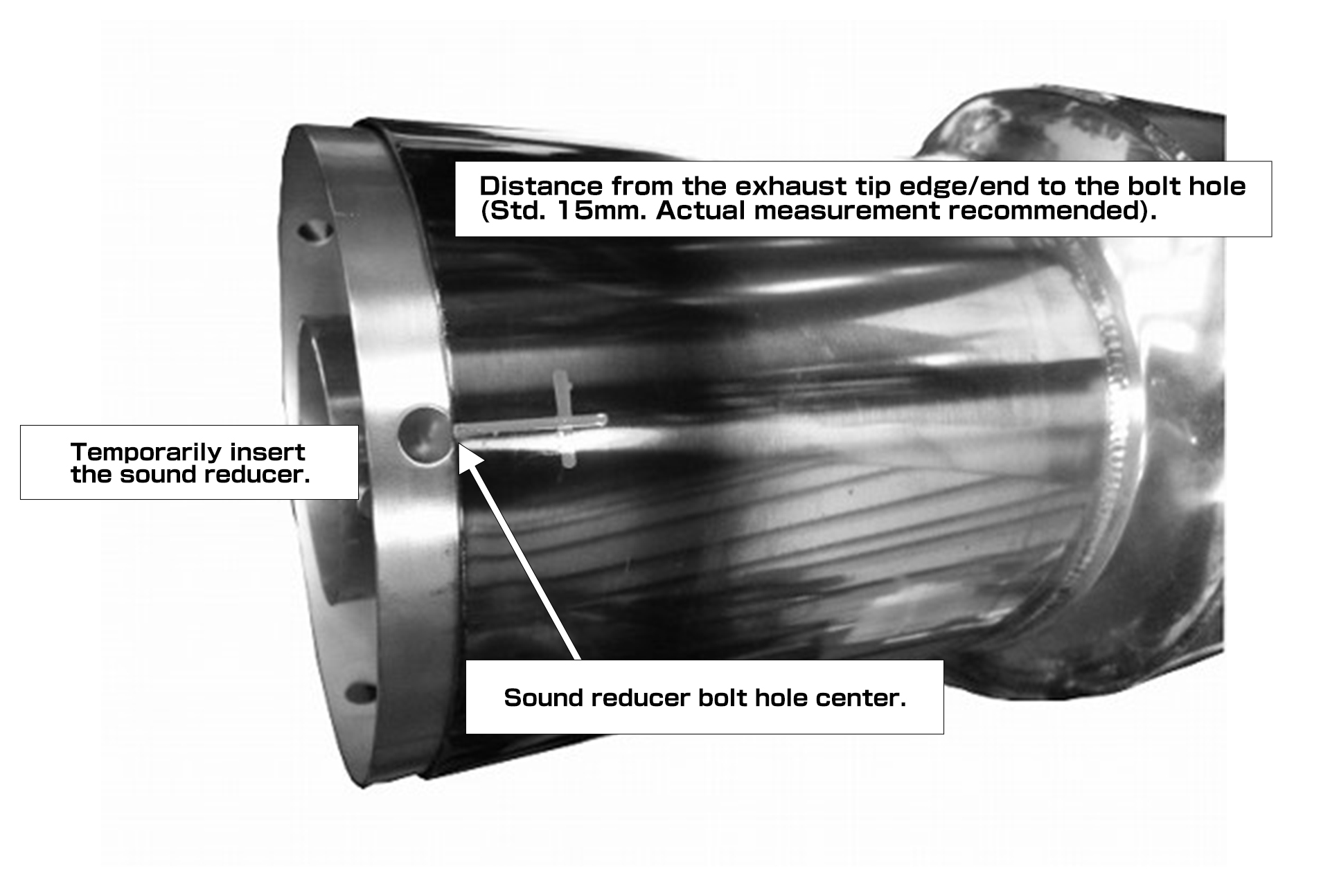
- 上図の基準穴を基に加工を行なう。
1. サイレンサー内部に切り粉が入らないようにウエス等で保護する。
2. テールエンド端面より基準穴があいている距離を確認する。(基準値15mm)
3. サウンドレデューサーを軽く差し込み穴位置センターをマーキングする。(2ヶ所)
4. 基準穴を合わせ、ボタンボルトM6・フランジナットM6でサウンドレデューサーを固定する。
この時、まっすぐに差し込まれているか、サウンドレデューサー穴位置が基準値
(15mm程度)にあるか、同時に確認する。(次頁マーキング位置図参照)
※ボタンボルトM6、フランジナットM6使用。
7. テールパイプTYPE-RとサイレンサーブラケットB LH/RHを仮組みする。
※・フランジボルトM8 L=25(P.9㉒) ・フランジナットM8(P.9㉔)使用。 ブラケットBがテールパイプのステーを挟むように装着してください。
リアバンパーとのクリアランスを確認しながら装着してください。
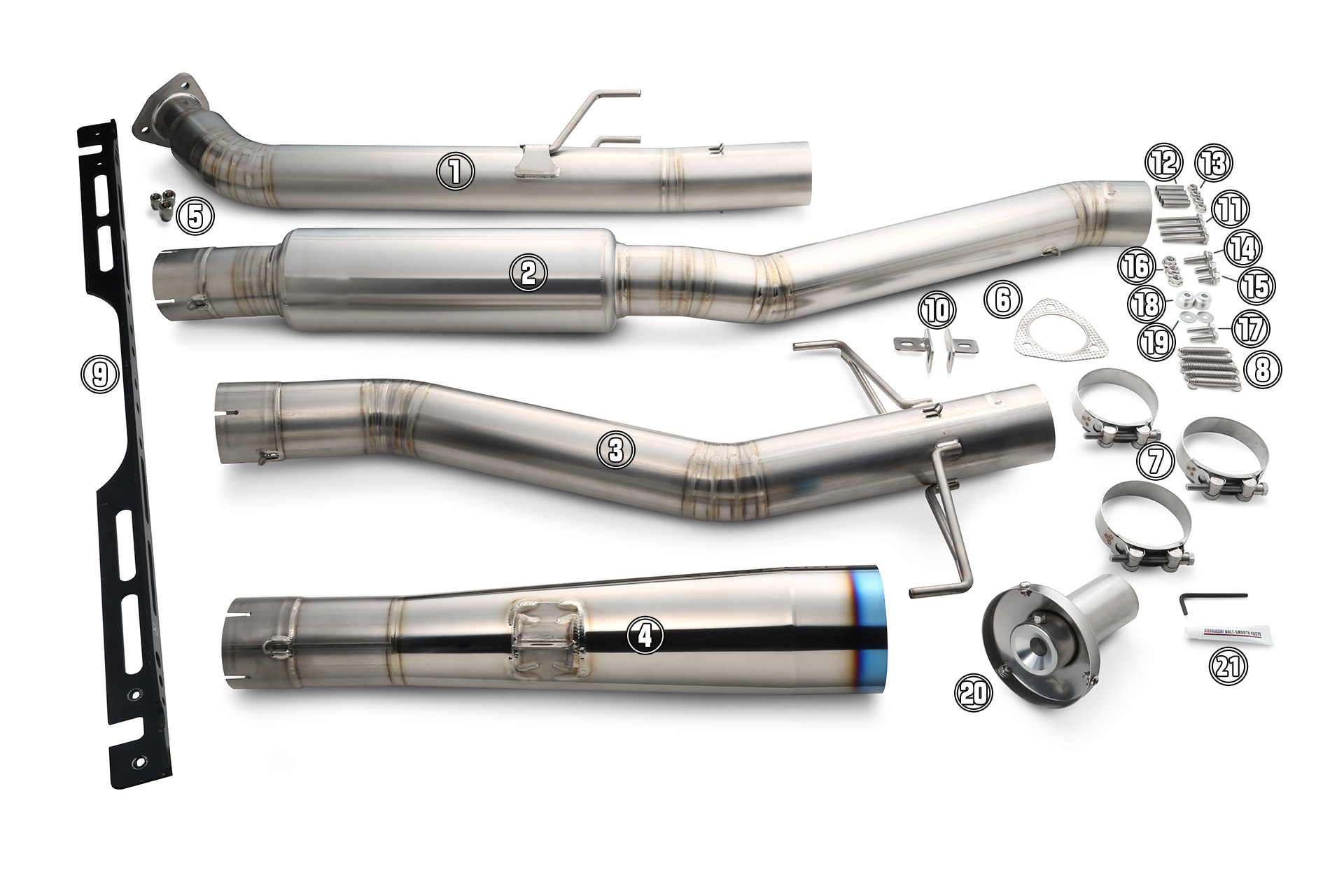
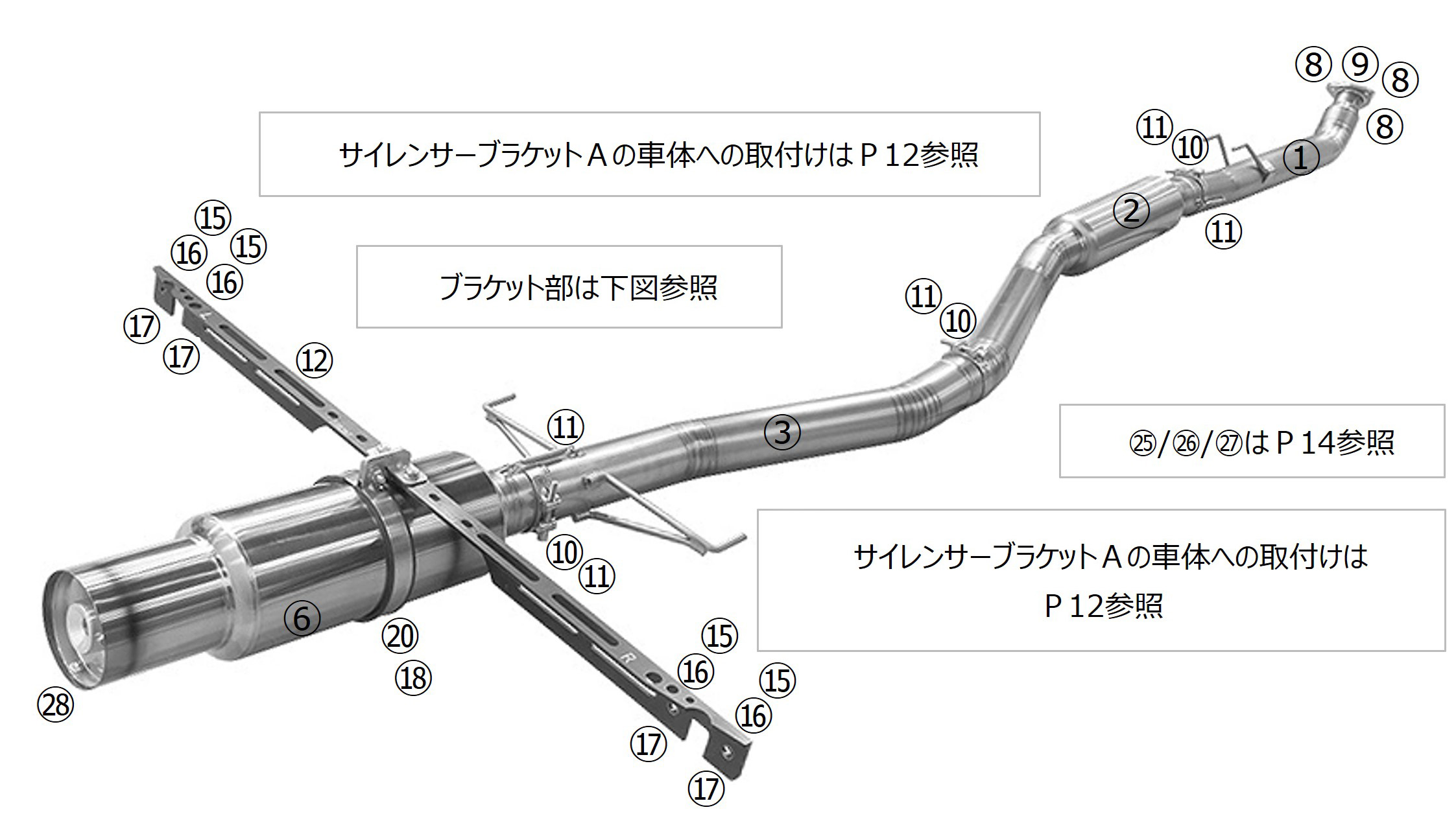
6. サイレンサーTYPE-Sにクランプバンドを通し、スプリングフック位置が平行になるようにメインパイプCに差し込む。
※サイレンサーTYPE-S(P.10⑥) ・クランプバンド(P.10⑩)使用。 サイレンサーASSYのプレスマークが真下にくるように装着してください。
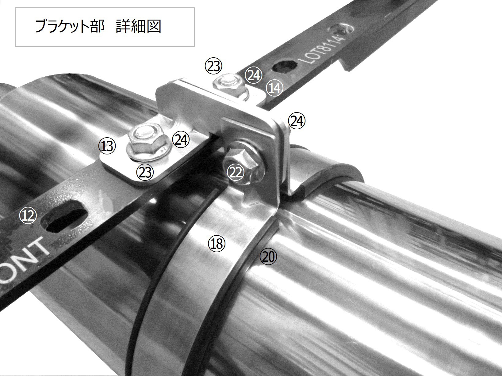
7. サイレンサーバンドにサイレンサーバンドラバーを取り付け、サイレンサーに傷をつけないように注意しながら、
サイレンサーブラケットB LH/RHに取り付ける。
※・サイレンサーバンド(P.10⑱) ・サイレンサーバンドラバー(P.10⑳)
・フランジボルトM8 L=25(P.10㉒) ・フランジナットM8(P.10㉔)使用。 サイレンサーバンドがブラケットBを挟むように装着してください。
リアバンパーとのクリアランスを確認しながら装着してください。
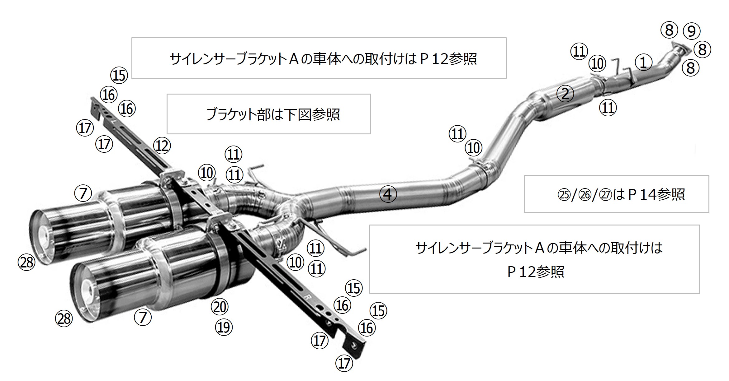
6. サイレンサーTYPE-Dにクランプバンドを通し、スプリングフック位置が平行になるようにメインパイプDに差し込む。
※サイレンサーTYPE-D(P.11⑦) ・クランプバンド(P.11⑩)使用。 サイレンサーASSYのプレスマークが真下にくるように装着してください。
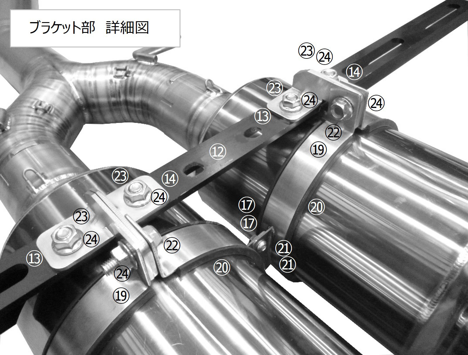
7. サイレンサーバンドにサイレンサーバンドラバーを取り付け、サイレンサーに傷をつけないように注意しながら、
サイレンサーブラケットB RH/LHに取り付ける。
※・サイレンサーバンド(P.11⑲) ・サイレンサーバンドラバー(P.11⑳)
・フランジボルトM8 L=25(P.11㉒) ・フランジナットM8(P.11㉔)使用。 サイレンサーバンドがブラケットBを挟むように装着してください。
リアバンパーとのクリアランスを確認しながら装着してください。
注 意
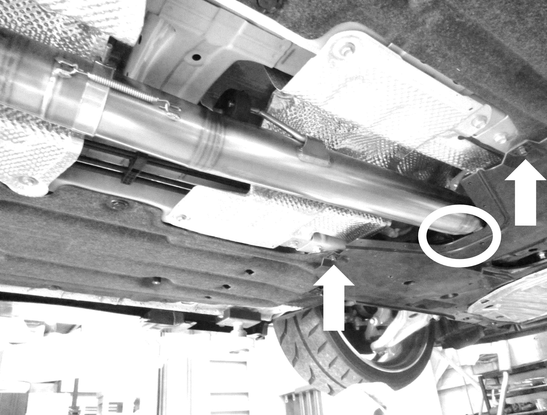
■車体各部とのクリアランスや、干渉のない事を確認してから本締めを行ってください。
なお、車両個体差により十分なクリアランスが得られない場合は、触媒の取り付けボルトを
各部が動く程度に緩め、本品の装着クリアランスを確保した後、本締めしてください。
■マフラーに油分などが付着した状態で使用すると、汚れや焼けの原因となります。
取付後は、必ず脱脂を行ってください。
■装着・使用状況により、周辺部品に熱害が及ぶ可能性があります。必要に応じ、遮熱対策を行ってください。
警 告
■サウンドレデューサーを取り付けたまま、高速走行を行わないでください。
サウンドレデューサーを取り付けたまま、高速走行を行わないでください。
■サウンドレデューサーの脱着は、マフラーが冷えた状態で行ってください。
警 告
■緩みや干渉があると性能の低下や、周辺部品が損傷し故障の原因となるため、確認は慎重に行ってください。
■排気漏れがあると、性能の低下や排気ガスによる中毒を起こす原因となり、危険です。
■走行中に異常を感じた場合は直ちに走行を中止し、確認を行ってください。
■その場で修復を行う場合は、エキゾーストシステムが十分に冷えた状態で行ってください。
■部品の脱落等が生じている場合は、エンジンを再始動せず、専門業者に修理を依頼し、指示に従ってください。
注 意
■本品を装着した際、車両仕様によってはエンジン特性に大きな変化がある場合があります。
装着後は、エンジンセッティングを確認し、必要に応じてそれらの再セッティングを行ってください。
This manual only provides basic instructions. For more details please refer to the vehicle's official factory service manual.
WARNING
■The exhaust tip has one predrilled bolt hole. However, when using QUIET MODE 2,
ensure you add the extra bolts and bolt holes to fully secure the sound reducer in place
as detailed in the installation manual. Whilst QUIET MODE 1, can be used with just one bolt,
using extra bolts is strongly recommended for added safety.
WARNING
■Failing to add/use the additional bolts may result in parts coming loose while driving
which can be extremely dangerous for vehicles directly behind and/or around you.
■This may also result in the exhaust tip becoming warped or damaged.
CAUTION
■Use the reference hole (as shown above) for guidance
when adding the extra bolt holes.
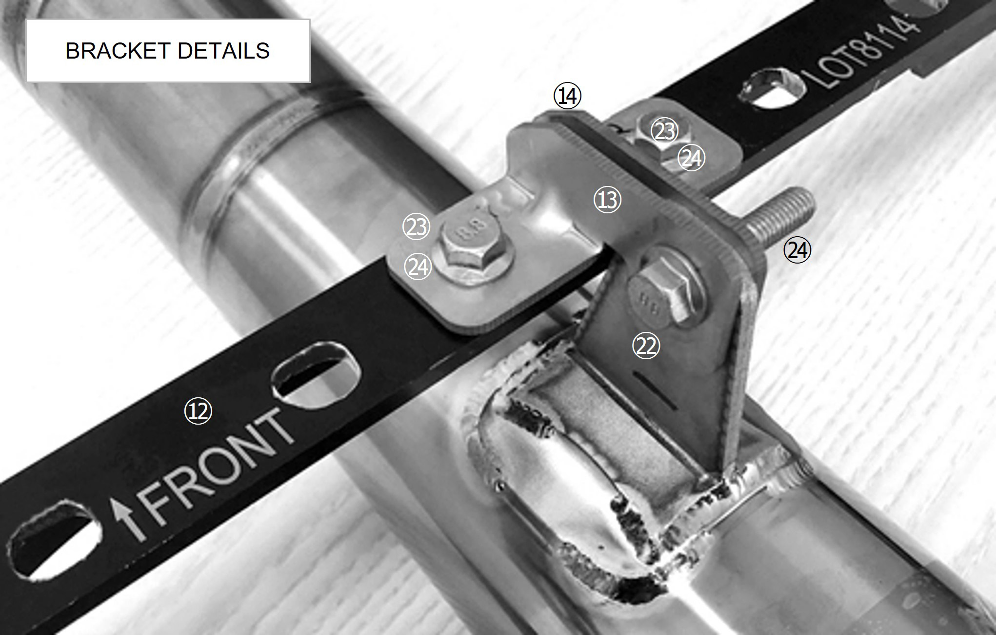
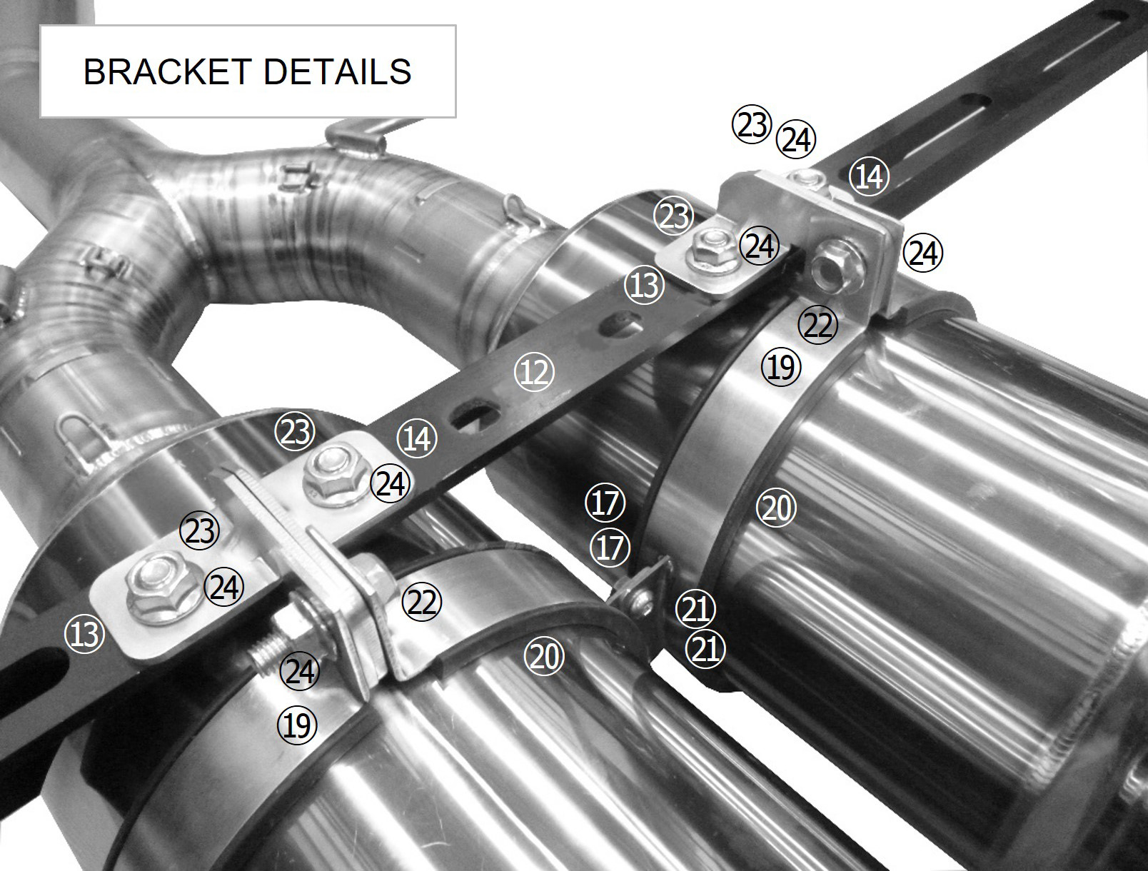
7. Loosely install SILENCER BRACKET B LH/RH onto TAIL PIPE TYPE-R.
※・FLANGE BOLT M8 L=25(P.23㉒) ・FLANGE NUT M8(P.23㉔) Install SILENCER BRACKET B LH/RH so that it clamps the bracket on the tail pipe.
During this process, ensure you check the clearance with the rear bumper.
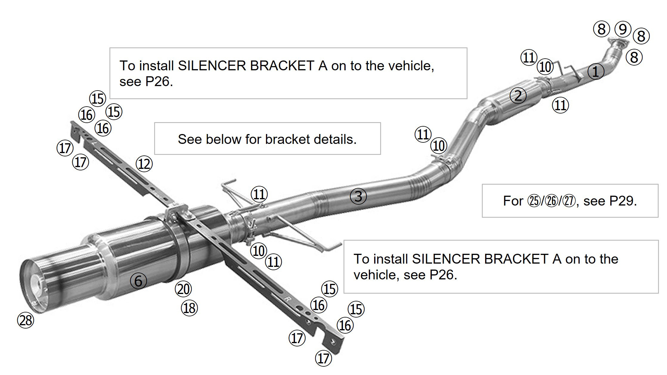
6. Attach the CLAMP BAND to SILENCER TYPE-S then slide onto MAIN PIPE C
ensuring the spring hooks align.
※SILENCER TYPE-S(P.24⑥) ・CLAMP BAND(P.24⑩) Ensure that the SILENCER is installed with the logo facing downwards.
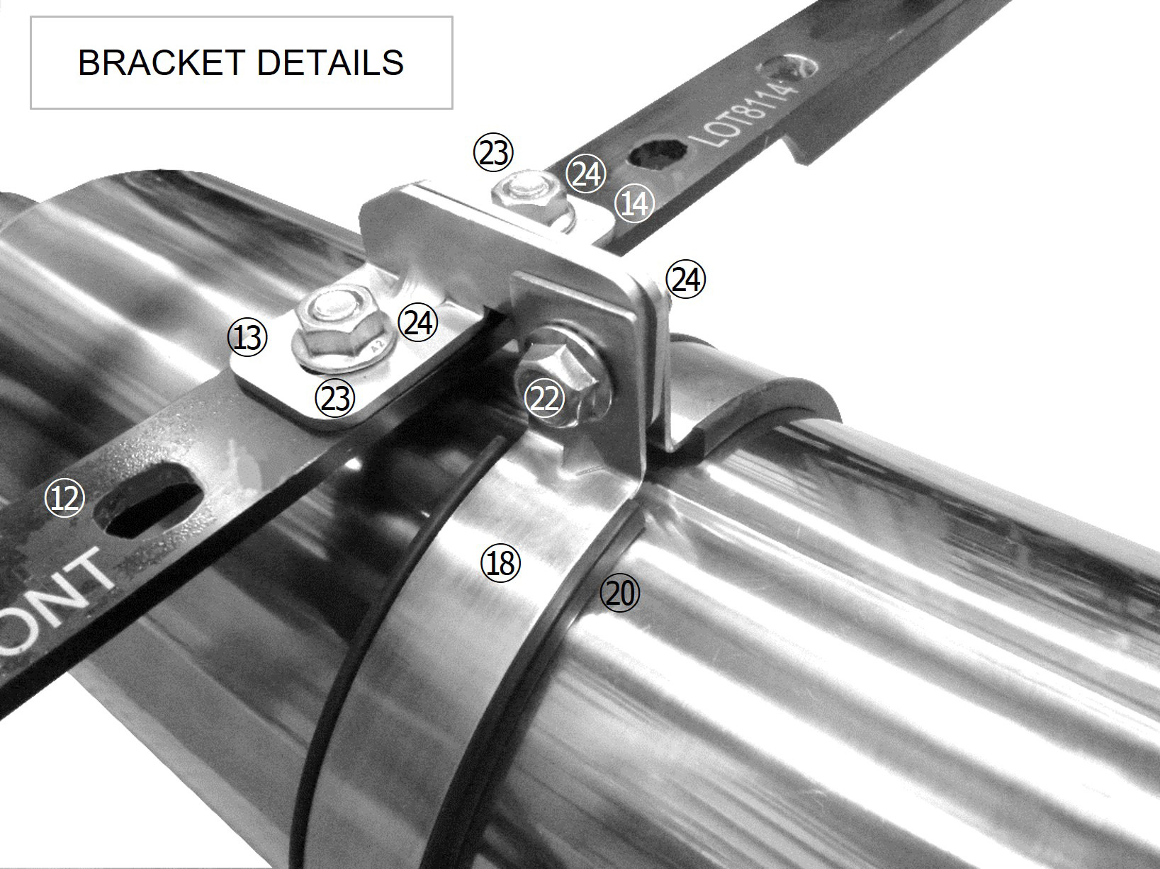
7. Attach the SILENCER BAND RUBBER to the SILENCER BAND. Then, install onto
SILENCER BRACKET B LH/RH, taking care not to scratch the SILENCER.
| ※ | ・SILENCER BAND(P.24⑱) | ・SILENCER BAND RUBBER(P.24⑳) |
| ・FLANGE BOLT M8 L=25(P.24㉒) | ・FLANGE NUT M8(P.24㉔) |
Install SILENCER BRACKET B LH/RH so that it clamps the bracket on the tail pipe.
During this process, ensure you check the clearance with the rear bumper.
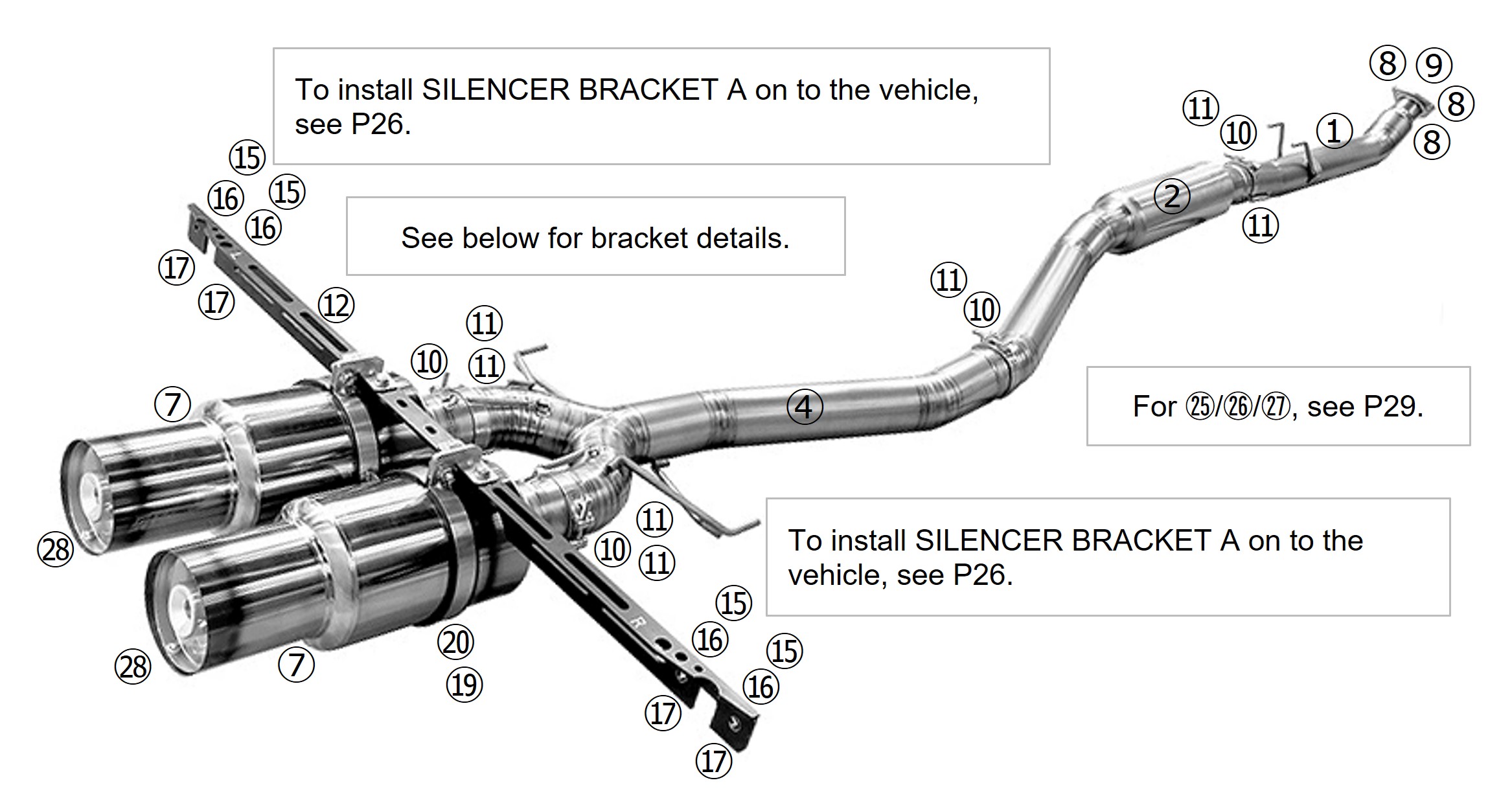
6. Attach the CLAMP BAND to SILENCER TYPE-D then slide onto MAIN PIPE D
ensuring the spring hooks align.
※SILENCER TYPE-D(P.25⑦) ・CLAMP BAND(P.25⑩) Ensure that the SILENCER is installed with the logo facing downwards.
7. Attach the SILENCER BAND RUBBER to the SILENCER BAND. Then, install onto
SILENCER BRACKET B LH/RH, taking care not to scratch the SILENCER.
| ※ | ・SILENCER BAND(P.25⑲) | ・SILENCER BAND RUBBER(P.25⑳) |
| ・FLANGE BOLT M8 L=25(P.25㉒) | ・FLANGE NUT M8(P.25㉔) |
Install SILENCER BRACKET B LH/RH so that it clamps the bracket on the tail pipe.
During this process, ensure you check the clearance with the rear bumper.
CAUTION
■Ensure sufficient clearance and correct fitment has been achieved before completely tightening
down the fastenings. In some cases, there may be insufficient clearance due to minor differences
between individual vehicles. In such a case, loosen the fastenings on the catalytic converter and
adjust the positioning until sufficient clearance is achieved before retightening the fastenings again.
■Ensure you clean the exhaust after installation. Using the exhaust whilst there is oil or other debris
on it can cause blemishes and/or burn marks.
■Depending on the installation and use of the exhaust, you may need to apply thermal insulation to
prevent heat damage to the surrounding components/areas.
WARNING
■Do not drive at high speeds with the SOUND REDUCER installed
as it may become damaged and/or broken.
■Only install/uninstall the SOUND REDUCER when the exhaust is cold.
WARNING
■Be thorough when performing checks as incorrect fitment or loose parts can result in reduced performance and/or damage to other surrounding parts and components.
■Exhaust leaks not only reduce performance but can also be a health hazard and should be addressed immediately.
■If there are any abnormalities whilst using the vehicle, stop immediately and check for faults.
■Ensure all exhaust related components have cooled before attempting any repairs.
■Do not restart the engine should you notice anything abnormal such as missing/broken parts.
CAUTION
■Once the product has been installed on the vehicle, the engine characteristics may change depending on the setup. After installation, adjust the engine/ECU settings as necessary.